New Technique Allows Real-Time Microscopy at High Heat and Loading
For Immediate Release
Researchers have demonstrated a technique that allows them to track microscopic changes in metals or other materials in real time even when the materials are exposed to extreme heat and loads for an extended period of time — a phenomenon known as “creep.” The technique will expedite efforts to develop and characterize materials for use in extreme environments, such as nuclear reactors.
“Until now, you could look at a material’s structure before exposing it to heat or load, then apply heat and load until it broke, followed by a microstructural observation. That means you’d only know what it looked like before and after loading and heating,” says Afsaneh Rabiei, corresponding author of a paper on the work and a professor of mechanical and aerospace engineering at North Carolina State University.
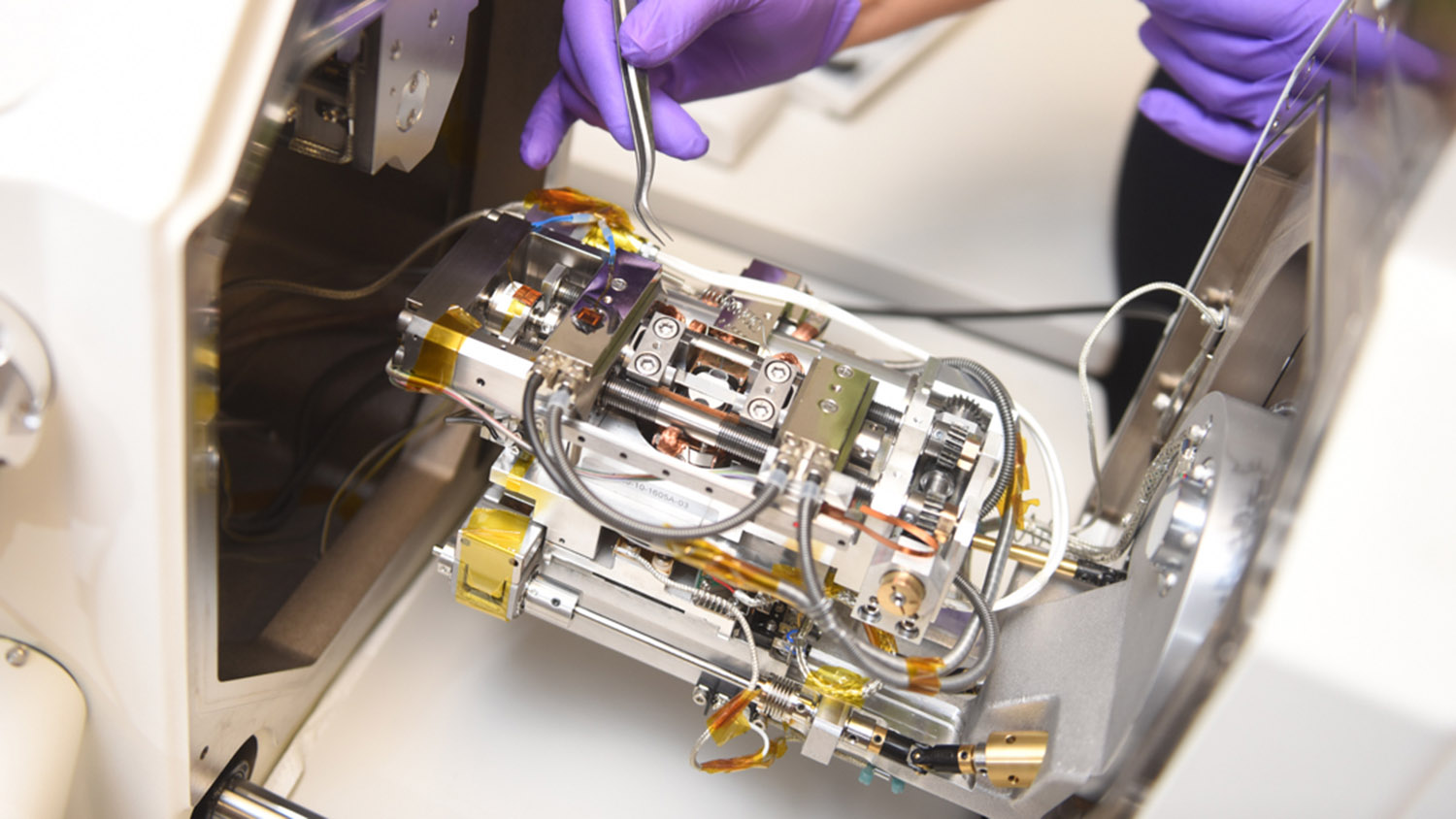
“Our technique, which is called ‘in situ scanning electron microscopy (SEM) heating and loading,’ allows us to see the microscopic changes taking place throughout the process. You can see how cracks form and grow, or how microstructure transforms during the failure process. This is extremely valuable for understanding a material’s characteristics and its behavior under different conditions of loading and heating.”
Rabiei developed the in situ SEM technique for high temperatures and load (tension) as a means of conducting high throughput assessments of the behavior of advanced materials. The goal was to be able to predict how a material responds under a variety of heating and loading conditions. The project was supported by the Department of Energy. The instrument can capture SEM images at temperatures as high as 1,000 degrees Celsius (C), and at stresses as high as two gigapascal – which is equivalent to 290,075 pounds per square inch.
For their recent demonstration of the technique’s potential, researchers conducted “creep-fatigue” testing on a stainless steel alloy called alloy 709, which is being considered for use in nuclear reactors.
“Creep-fatigue testing involves exposing materials to high heat and repeated, extended loads, which helps us understand how structures will perform when placed under loads in extreme environments,” Rabiei says. “That is clearly important for applications such as nuclear reactors, which are designed to operate for decades.”
To that end, Rabiei and her collaborators tested samples of alloy 709 at temperatures of 750 degrees C, which experienced repeated load cycles ranging from holding the load for one second to holding the load for one hour repeatedly until they failed. In one iteration, where the sample was repeatedly exposed to a load for one hour, with seven-second intervals between loads, the experiment lasted for more than 600 hours. And the in situ SEM captured it all.
“In situ SEM allowed us to track the microscopic development of cracks in the material and the evolution of the microstructure during the creep-fatigue testing,” Rabiei says. “We were then able to use these data to model what alloy 709’s behavior would be over years of use in a nuclear reactor. And alloy 709 outperformed 316 stainless steel, which is what’s currently used in many reactors.
“That’s good news, but what is most exciting here is the methodology we used. For example, our in situ SEM technique allowed us to witness the role that micro-structural details called twin boundaries play in controlling crack growth in alloy 709. Our observations showed that when a crack reaches such twin boundaries in alloy 709, it redirects itself and takes a detour. This detouring effect delays crack growth, improving the material’s strength. Without our in situ SEM heating and loading technology, such observations could not be possible. Moreover, using this technique, we only need small specimens and can generate data that normally take years to generate. As such we are saving both time and the amount of material used to evaluate the material’s properties and analyze its failure process.
“The ability to capture insights like these is a significant advance for research into any number of new, high-performance materials, particularly those that are designed to perform in extreme environments,” Rabiei says.
The paper, “Performance of alloy 709 under creep-fatigue at various dwell times,” is published in the journal Materials Science and Engineering: A. First author of the paper is Amrita Lall, a Ph.D. student at NC State. The paper was co-authored by Siddhartha Sarkar, a Ph.D. student at NC State; and by Rengen Ding and Paul Bowen of the University of Birmingham.
The work was done with support from the U.S. Department of Energy’s Nuclear Energy University Program under award number 2015-1877/DE-NE0008451; and from the Research Councils UK (now UK Research and Innovation) under award number EP/N016351/1.
-shipman-
Note to Editors: The study abstract follows.
“Performance of alloy 709 under creep-fatigue at various dwell times”
Authors: Amrita Lall, Siddhartha Sarkar and Afsaneh Rabiei, North Carolina State University; Rengen Ding and Paul Bowen, University of Birmingham
Published: June 16, Materials Science and Engineering: A
DOI: 10.1016/j.msea.2019.138028
Abstract: A comprehensive experimental evaluation of the creep-fatigue behavior of Alloy 709 at 750°C is reported in this study. Alloy 709 is a 20Cr–25Ni austenitic stainless steel, with high temperature creep strength and corrosion resistance, which can potentially be used in structural components of nuclear power plants. Creep-fatigue crack growth (CFCG) experiments were conducted using in-situ heating-loading and Scanning Electron Microscope (SEM) equipped with Electron Backscatter Diffraction (EBSD) detector. To study the “real-time” CFCG behavior of alloy 709 at 750°C with varying dwell times in vacuum, flat dog bone samples were prepared. A starter notch was added, and a pre-crack was introduced by high frequency fatigue cycles at room temperature. Prior to loading and heating the entire area ahead of the crack tip was mapped using EBSD. These maps were utilized to generate a set of Coincident Site Lattice (CSL) boundary maps from the area ahead of the crack tip. Upon completion of the EBSD and CSL mapping, the heating and loading of samples took place in the SEM. During the experiment, crack growth was monitored on the surface of the sample using SEM imaging and data were transferred over to the CSL maps to highlight the crack path with respect to the grain boundary and precipitations arrangement in the sample. Some samples went through EBSD-CSL mapping before heating and loading along with Transmission Electron Microscopy (TEM) imaging post heating and loading. Comparing the CSL maps before and after crack growth provided additional details about the dependence of crack path and crack growth mode on microstructure, primarily grain boundary character, and dwell time. TEM analysis of the microstructure after the crack growth was employed to validate the findings of the in-situ heating and loading SEM data. Real-time monitoring of microstructural phenomena, such as void nucleation, grain boundary cavitation, slip activation, and resistance of twin boundaries to cracking during CFCG tests, sheds a new light on the crack growth mechanism. The results indicated that at lower dwell times, the crack mainly propagates in a transgranular fashion, with the aid of slip lines. At higher dwell time, intergranular cavitation dominates the crack growth. However, as more than 50% of grain boundaries are coherent twin boundaries, which are low energy boundaries resistant to cavitation, crack growth is delayed when reaching such boundaries and hence twin boundaries may impart some resistance to crack propagation in Alloy 709 at high temperatures.
- Categories: